Dsc Pc1616 Installation Manual
- Dsc Pc1616 Installation Manual Pdf
- Dsc Power Series Pc1616 Installation Manual
- Dsc Pc1616 Installer Code
- Dsc Pc1616 Installation Manual
- Dsc Pc1616 Installation Manual Download
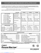
DSC - PC1550 (Installation Manual) Installation Manual DSC PC1550 - This Installation Manual provides instructions on how to setup, mount and install the product. Reading the Official Installation Manual is the safest way to preserve the legal guarantee in setting up the product properly. DSC Powerseries PC1616/PC1832/PC1864 v4.6 NA Installation Guide. This Installation Guide provides the basic installation, wiring and programming information required to program the PowerSeries PC1616, PC1832, and PC1864 control panels.
Download Operation & user’s manual of DSC PowerSeries PC1616 Control Panel, Network Router for Free or View it Online on All-Guides.com. This version of DSC PowerSeries PC1616 Manual compatible with such list of devices, as: PowerSeries PC1616, PowerSeries PC1832, PC1616; PC1832; PC1864, PowerSeries PC1864
Brand: DSC
Category: Control Panel , Network Router , Other , Security System
Type: Operation & user’s manual
Model: DSC PowerSeries PC1616 , DSC PowerSeries PC1832 , DSC PC1616; PC1832; PC1864 , DSC PowerSeries PC1864
Pages: 28 (1.81 Mb)
Related Products for DSC PowerSeries PC1616
Related Manuals for DSC PowerSeries PC1616
DSC PowerSeries PC1616: Frequently viewed Manuals
Hardware Installation
Begin the installation by mounting the cabinet in a dry protected area with access to unswitched AC power.
Install Hardware in the sequence indicated below. Do NOT apply power until installation is complete.
NOTE: All wiring entry points are designated by arrows. All circuits are classified UL power limited except for the battery leads.
Minimum 1/4” (6.4mm) separation must be maintained at all points between power limited and non-power limited wiring and
connections.
1. Keybus Wiring
The 4-wire KEYBUS (red, black, yellow and green) is the communication connection between the control panel and all modules. The 4 KEY-
BUS terminals of all modules must be connected to the 4 KEYBUS terminals of the main control panel.
The following rules must be followed when wiring the Keybus:
•
Minimum 22 AWG wire, maximum 18 AWG (2-wire twisted pre-
ferred
•
Do NOT use shielded wire
•
Modules can be home run, connected in series or can be T-
tapped provided that the maximum wire distance from the control
panel to any module does not exceed 1,000 feet (305m)
•
Dsc Pc1616 Installation Manual Pdf
No more than 3,000 feet (915m) of wire can be used in total
2. Zone Wiring
Zones can be wired for Normally Open, Normally Closed Contacts
with Single-end-of-line (SEOL) resistors or Double End-of-Line
(DEOL) resistors. Observe the following guidelines
•
For UL Listed Installations use SEOL or DEOL only.
•
Minimum 22 AWG wire, maximum 18 AWG
•
Do NOT use shielded wire
•
Wire run resistance shall not exceed 100
Ω.
Refer to the chart
below.
•
Section [001-004] Selects Zone Definition
•
Section [013] Opt [1] Selects Normally Closed or EOL resistors
•
Section [013] Opt [2] Selects Single EOL or Double EOL resis-
tors. Hp pro 3500 drivers.
Zone Status
Loop Resistance
- 0
Ω (shorted wire/loop)
- 5600
Ω (contact closed)
- infinite (broken wire, open)
- 11,200
Ω (contact open)
Loop Status
Fault
Secure
Tamper
Violated
3. Bell Wiring
These terminals supply 700mA of current at 12V
DC
for commercial
installations and 11.1-12.6 V
Dsc Power Series Pc1616 Installation Manual
DC
for residential installations (e.g.DSC
SD-15 WULF). To comply with NFPA 72 Temporal Three Pattern
requirements:
Program Section [013] Opt [8]ON.
The Bell output is supervised and power limited. If unused, connect a
1000
Ω resistor across Bell+ and Bell- to prevent the panel from dis-
playing a trouble. See [
✱][2].
NOTE: Bell output is current lim-
ited by 2A PTC
NOTE: Steady, Pulsed and Tem-
poral Three Pattern alarms are
supported.
CONTROL
PANEL
150’ (46m)
150’ (46m)
500’ (152m)
500’ (152m)
Normally Closed Loops - Do NOT use for UL Installations
Single End-of-Line Resistor Wiring
Double End-of-Line Resistor Wiring
OBSERVE
POLARITY
BELL/SIREN
700mA (max.)
Dsc Pc1616 Installer Code
Dsc Pc1616 Installation Manual
